PIC curcuit board sketches
Posted Wed, Aug 3, 2005 at 11:45 PM
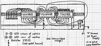
I think anyone who reads this blog should know by now that I absolutely suck at drawing "real" electronics schematics...
So here's a couple of sketches using the PIC chip instead of the Basic Stamp. Meant to post these a long time ago -- sorry.
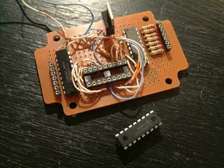
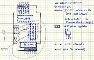
The version below uses a vector board in order to get a more permament curcuit. I didn't want to solder my PIC chip right into the board (otherwise, I wouldn't ever be able to re-program them), so instead I used header pins as placeholders. Solder those into the board instead and pop the PIC chips in and out as needed. Great for the wires to the LED matrix and serial comm port too.
You can buy blank vector boards at Supremetronics on Queen Street West for 65 cents each. 18-pin machine pins were $0.70 each. You can get a single line of 32-pins too -- $1.15 each.
Cheap and easy if you're making one or two boards. If you're making more, I highly recommend just shelling out the extra cash upfront for printed curcuit boards (PCBs). (And I speak from personal experience here! It took me a full 3-4 days to make only 10 vector board curcuits.)
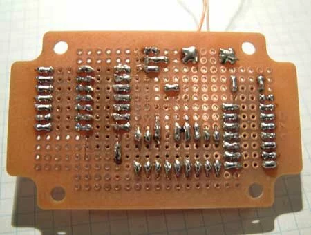
Electrical connections are made by bending any available wires or leads so they touch or almost touch. A dab of solder will keep it in place and bridge any gaps. (I kind of overdid it... you really don't need to glob on so much solder.)